AutoCAD Object Selection Methods
One of the ways to select objects is to select them individually, which can be time-consuming, if you have a number of objects to edit. This problem can be solved by creating a selection set that enables you to select several objects at a time. The selection set option can be used with those commands that require objects selection, such as ERASE and MOVE. There are many object selection methods, such as All, Last, Add, and so on. At this point, you will learn two options: Window and Crossing.
The Window Option in AutoCAD
This option is used to select an object or group of objects by enclosing them in a box or window. The objects to be selected should be completely enclosed within the window; those objects that lie partially inside the boundaries of the window are not selected. You can select the Window option by typing W at the Select Objects prompt. You are prompted to select the two opposite corners of the window. After selecting the first corner, you can select the other corner by moving the cursor to the desired position and specifying the particular point. As you move the cursor, a blue shaded window is displayed that changes in size as you move the cursor. The objects selected by the Window option are displayed as dashed objects.

The prompt sequence for using the Window option with the ERASE command is given next.
Command: ERASE
Select objects: W
Specify first corner: Select the first corner.
Specify opposite corner: Select the second corner.
Select objects: Hit the enter key
You can also involve the Window option by selecting a blank point on the screen at the Select objects prompt. This is automatically taken as the first corner of the window. Moving the cursor to the right will display a blue shaded window. After getting all the objects to be selected inside the window, you can specify the other corner with your pointing device. The objects that are completely enclosed within the window will be selected and highlighted. The following is the prompt sequence for automatic window selection with the ERASE command.
Command: ERASE
Select objects: Select a blank point as the first corner of the window.
Select opposite corner: Drag the cursor to the right to select the other corner of the window.
Select objects: Hit the ENTER key.
The Crossing Option in AutoCAD
This option is used to select an object or group of object by creating a box or window around them. The objects to be selected should be touching the window boundaries or completely enclosed within it. You can invoke the Crossing option by entering C at the Select objects prompt. After you choose the Crossing option, AutoCAD prompts you to select the first corner at the Specify first corner prompt. Once you have selected the first corner, a shaded dashed box or window of green color is drawn. By moving the cursor, you can change the size of the crossing box, hence putting the objects to be selected within (or touching) the box. Here, you can select the other corner. The objects selected by the Crossing option are highlighted by displaying then as dashed objects, Figure below. The following prompt sequence illustrates the use of the Crossing option when you choose the Erase button.

Select objects: C
Specify first corner: Select the first corner of the crossing window.
Specify opposite corner: Select the other corner of the crossing window.
Select objects: Hit the ENTER key.
You can also select the Crossing option automatically by selecting a blank point on the screen at the Select objects prompt and moving the cursor to the left. The blank point you selected becomes the first corner of the crossing window and AutoCAD will then prompt you to select the other corner. As you move the cursor, a green shaded box or window drawn with dashed lines is displayed. The objects that are touching or completely enclosed within the window will be selected. The objects selected by the Crossing option are highlighted by being displayed as dashed objects. The prompt sequence for automatic crossing selection when you choose the Erase button is given next.
Select objects: Select a blank point as the first corner of the crossing window.
Specify opposite corner: Drag the cursor to the left to select the other corner of the crossing window.
Select objects: Hit the ENTER key.
Note:
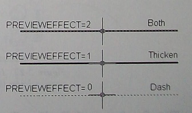
In AutoCAD, the entities are highlighted when you move the cursor over them. This features is known as the selection preview. The settings for the selection preview are available in the Selection Preview area of the Selection tab of the Options dialog box. The PREVIEWEFFECT variable store the type of appearance during highlighting. The preview will be a Dashed Line if the variable is set to 0, Thicken Line if it is set to 1, and Dashed Thicken Line, if it is set to 2. The selection preview for different values of the PREVIEWEFFECT variable is shown below.
Comments