Solid Modeling Tutorial 1 in AutoCAD
Let's draw a solid model using some of the commands. You construct, edit, and display the model as a solid object. The figure below illustrates the finished model.

The completed model, rendered.
The figure below shows the dimensions of the 3D object. You may want to refer to it as you construct the base model from solid primitives.

The dimensions of the model
Before drawing any object, analyze it to determine the best primitives to use. In this tutorial, you use both solid modeling commands and some 3D principles to construct the model. The figure below illustrates the building block components used to "assemble" the model.
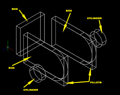


The solid model components
1. Start AutoCAD with a new drawing.
Set snap to 0.5
2. Select Box from the Draw | Modeling menu, and enter the points indicated in the following command sequence.
Command: box
Select the first corner of the box.
Specify corner of box of [CEnter] <0,0,0>:3,2
Define the location of the opposite corner of the box.
Specify corner or [Cube/Length]:@5,0.5
Now define the height of the box
Specify height: 3

Constructing the first leg with a solid model box.
3. Repeat the Box command. Refer to the figure for the points to enter.
Command: (Press spacebar to repeat the command.)
BOX Specify corner of box or [CEnter] <0,0,0>: (Select point 1.)
Specify corner or [Cube/Length]: @0.5,3
Specify height: 3

Adding a second box.
4. Use the VPOINT command to rotate the view so you can complete your work.
Command: vpoint
Current view direction: VIEWDIR=0.0,0.0,1.0
Specify a view point or [Rotate]
Enter angle in XY plane from X axis <0>: 290
Enter angle from XY plane <0>: 23
5. Use a zoom factor to "zoom out" the display of the drawing.
Command: zoom
Specify corner of window, enter a scale factor (nx or nXP), or [All/Center/Dynamic/Extents/Previous/Scale/Window]

Rotating the viewpoint gives a better view of the model.
6. Add a drill hole to the side of the object. Begin by setting the UCS icon so you can see the origin of the UCS UCS you will be working in.
Select Tools menu > New UCS> 3 Point

7. Change the UCS to the lower-left corner of the model.

Changing the UCS with the 3-point method.
8. Now add the drill hole with the CYLINDER command.

Holes start out as cylinders.
Command: cylinder
Specify the center point of the cylinder. Note that the absolute coordinate you use are relative to the origin of the new UCS.
Specify center point of base or [3P/2P/Ttr/Elliptical]: 3.5,1.5
Specify the radius of the cylinder.
Specify base radius or [Diameter]: 0.75
Designate the extrusion height of the cylinder. Since you want the extrusion to extend in a negative direction, the value is negative.
Specify height or [2Point/Axis endpoint]: -0.5
9. Rather than draw the second leg, make a copy of the first leg (with the cylinder):
Set the UCS back to "World."
Start the COPY command.
Select the first box and its cylinder, and then specify a displacement of @3.5<90.
 Copying the first leg to make the second leg.
 10. Combine the solids as a single composite body. To do this, you must cange the three boxes into a single solid object, and then subtract the cylinders that make the drill holes. You first use the UNION command to combine the boxes.
Command: union
Select Objects: (Select all three boxes and press enter)
AutoCAD performs the necessary calculations to combine the boxes into a single solid object. You will notice that, when the drawing is redisplayed, the edge lines between the boxes are no longer a part of the object.

Union the three boxes into a single body
11. Subtract the cylinders from the object with the SUBTRACT command.
Command: subtract
Select solids and regions to subtract from...
Select objects: (Select the unioned boxes.)
Select objects: (Press ENTER.)
1 solid selected Select solids and region to subtract...
Select objects: (Select each of the cylinders.)
Select objects: (Press ENTER)
AutoCAD removes the cylinders from the solid body created by the union of the three boxes. You will not see a difference.

Subtracting cylionders from bodies creates round holes.
12. Next, fillet the corners.
 Fillet the ends of the legs.
 It may be easier to select the edges with snap turned off, and to zoom in closer.
Command: fillet
Current settings Mode=TRIM, Radius = 0.50
Select first object or [Polyline/Radius/Trim]: (Select point 1)
Enter fillet radius <0.5000>: 1.5
Select an edge or [Chain/Radius]: (Select point 2)
Select an edge or [Chain/Radius]: (Press ENTER)

One leg filleted...
You may need to use the REGEN command to clean up the view.
13. Now use the FILLET command again to fillet the back leg of the object.

... and both legs filleted.


Comments