Posts

Mastering Absolute Coordinate System in AutoCAD

Image
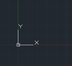
Using AutoCAD, precise locations of points within a drawing are determined using an absolute coordinate system. Establishing fixed reference points in relation to a predefined origin point allows for accurately creating and positioning objects in the drawing environment.   What is the Absolute Coordinate System? AutoCAD's coordinate system centers around the fundamental concept of absolute coordinates, which determine the precise placements of points in a drawing about a fixed origin point. Let's explore the essential elements:   Origin Point: The origin point (0,0) is the reference point from which all other coordinates are measured. By default, it is typically located at the lower-left corner of the drawing area.           X and Y Axes:  AutoCAD adopts the Cartesian coordinate system, where the X-axis symbolizes horizontal distances,  and the Y-axis signifies vertical distances. The system's positive values stretch towards the right on the X-axis and

Brick Seamless Texture for SketchUp

Image
DESCRIPTION Free seamless brick Vismat complete with maps: diffuse and bump for your SketchUp project. TECHNICAL INFORMATION Compatibility:  SketchUp and Vray for SketchUp File Format:     .jpg Download:       zip file, 1.6MB

35 Free Gold Photoshop Layer Style

Image
Download a set of free 35 gold Photoshop layer style made by Andrei-Oprinca . This set was designed to be used on text rather than larger shapes. Click here to download these free Photoshop layer style.

Photoshop Tutorial: Dispersion Effect

Image
This tutorial is called Photoshop dispersion effect by Photoshop Tutorial .

Free AutoCAD Tutorial Using Polar Tracking and PolarSnap

Image
Download Sample Drawing   Download and open M_Roller.dwg   On the status bar, make sure the following settings are on: 1. Snap 2. Polar tracking 3. Object snap Right-click Polar Tracking and select Settings.   In the Drafting Settings dialog box, Polar Tracking tab: Select 15 from the Increment Angle list. Under Polar Angle Measurement, click Absolute.   On the Snap and Grid tab: Click PolarSnap. Enter 1 in the Polar Distance field.   On the Object Snap tab: Make sure Endpoint and Node are selected. Click OK.   To draw the line using polar tracking: Activate the Line tool. 1. Specify the line's start point from the point object, using the Node object snap override. 2. Drag the cursor to the right until the polar tracking tooltip reads 25.00 < 0 degrees . Click the point.   Position the cursor so that the polar angle tooltip reads 15.00 < 45. Click the point.   Position the cursor so that the polar ang

Free AutoCAD Tutorial Using Object Snap

Image
1. Download Free AutoCAD Tutorial Object-Snaps.dwg and Open. 2. On the status bar, make sure the following settings are on: Object snap Dynamic input 3. To set object snaps: On the status bar, right-click Object Snap. Click Settings. In the Drafting Settings dialog box, Object Snap tab, set the running object snaps as shown in the following illustration. Clear all object snaps in the column on the right-side. Click OK. 4. To draw a line: On the Home tab, click Draw panel > Line. Select the endpoints as shown in the following illustration. Notice the appearance of the object snap. Press ENTER to end the Line command. Tip : You may need to use zoom and pan in order to view and snap to the correct points. 5. Press ENTER to repeat the Line command. Use the Endpoint object snap to create another line right next to the previous one. 6. To draw a circle: On the Home tab, click Draw panel > Circle. Touch the outer circle and you should see the Center snap

Creating A Basic Object in AutoCAD

Image
In this part of the exercise, you begin to draw the front view of the bracket, beginning at point (1) and ending at point (2). Then, you resume drawing from point (1) to point (3).   1. Create a New Drawing. Use acadiso.dwg as template (Metric). 2. On the status bar, make sure the following settings are on: Polar tracking Object snap Object snap tracking Dynamic input   3. Begin the line at point (1): On the Home tab, click Draw panel > Line or on the Command Line, type L or Line Enter 100, 50 . Press ENTER. Enter 100 . Press TAB. Enter 0 . Press TAB. Note: The values should appear in the Input interface as shown in the following image. Click to create the line. 4. Draw a second line perpendicular to the first: Drag the cursor upwards and enter 100 . Press TAB. Make sure the angle field displays 90 degrees, then click to draw the line. 5. Draw another line: Drag the cursor to the left making